What's new

Milling & Machining

Congratulations.

What does a new set of hand wheels cost?
There's nothing wrong with the handwheels, I'm just really clumsy on the mill vs my lathe that I'm used to. Purely a self inflicted mental block. Lots of new stuff happening at once combined with my poor attention focusing 😁

Cleaned up ok. First time using a boring head. That was pretty fun! My cheap boring bars flexy little dudes for sure.

IMG-20230520-WA0000.jpeg
 
Surface finish is trash. The cutter is hooched and I don't know what in the heck I'm doing. Not comfortable at all with the graduations on the handwheels and too cheap to spring for a DRO. Planned out the order of operations in such a way that I could use a dial indicator on a mag base to measure over to my next cut. Nailed every dimension to within 0.001". I'm happy with that!
Congratulations on your accuracy. But dam those are some ugly surfaces. What were you using for cutter? What were you using for feed and cutter speed?
 
Also worth checking the spindle tram. It sure is nice to see that needle land right on dimension :-)
 
I just like the color- 660 bronze bushing, split so each half goes in its respective cap. Its a bearing for the compounding lever on a 1920's screw press.


IMG_20230513_154302.jpg
 
Surface finish is trash. The cutter is hooched and I don't know what in the heck I'm doing. Not comfortable at all with the graduations on the handwheels and too cheap to spring for a DRO. Planned out the order of operations in such a way that I could use a dial indicator on a mag base to measure over to my next cut. Nailed every dimension to within 0.001". I'm happy with that!


IMG-20230519-WA0015.jpeg


AR ish Jig?

What does your bead blaster rig look like?
 
Congratulations on your accuracy. But dam those are some ugly surfaces. What were you using for cutter? What were you using for feed and cutter speed?
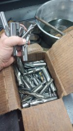
This is the jumbled up box of cutters I was given with the machine. I used the best looking one I could find, but you can imagine their state just by looking at this picture. 😁

Had the spindle running at 2500 rpm , which is max for my machine. 3/4" diameter, 4 flute hss cutter.

I was comforting to see a nice, shiny surface when single point cutting the bored hole after gnawing away the rest of the block.
 

Attachments

  • IMG-20230519-WA0011.jpeg
    IMG-20230519-WA0011.jpeg
    1.6 MB · Views: 3
Last edited:
AR ish Jig?

What does your bead blaster rig look like?
It's a rear axle block for a bike. I'm going to make a chain guard and this extended axle block is what it will mount to.

Sandblaster is the big floor model that Harbor Freight sells. It's been flawless and has seen heavy use.
 
My chip evacuation is a paint brush held in my other hand. You're giving me way too much credit, man!
 
The part I'm making now is getting powder coated satin black to help hide it, which requires a blasted surface for adhesion anyway. It all works out in the end.
 
I learned something today.

Trying to make sense of the graduations on the rotary table. Couldn't come up with any logical ideas, so hit YouTube for help.

Degrees
Seconds
Minutes
One minute = One degree

What?


YouTube comments: " Thanks for the video, it makes perfect sense now!"

No it doesn't. It does NOT make perfect sense at all.

What's halfway between 10° and 11° ?

10.5°? No. Hell no.

10° and 30 seconds. That's what.

Unbelievable. We just decided to throw decimals away? It's a mill accessory. The mill existed first. You couldn't imagine having dials that worked the same way would, I don't know, be sensible?

"Hey, how are we gonna mark these handwheels? Same as the other machines?"

"Nah, label it like a clock and just pretend it's normal"

It's not fucking normal. No wonder all the old gray hair shop wizards are so grumpy. They've had to put up with some silly shit.
 
I have a rotary table with a scale I have to relearn each time I use it- marks every 2/10ths of a minute which is crazy-making when trying to work in degrees. I suppose if you really wanted a base 10 angular system you'd use gradians but thats math-nerd stuff, not what I want on a machine.
 
Last edited:
It gets even weirder on dividing heads- degrees is the coarse measure, then you adjust the crank pointer on a ring of holes on a dividing plate, then calculate the number of holes to traverse over to obtain the final fractional degree. Old-school pros would move forward on one ring and backwards on another to get <really> precise angular offsets.

OTOH perhaps the hole ring method is a good compromise; you have to resolve the minutes/seconds to a given hole ring and # of holes in advance so when you're working with the tool the problem turns into counting the # of holes and revolutions of the crank.
 
Surface finish is trash. The cutter is hooched and I don't know what in the heck I'm doing. Not comfortable at all with the graduations on the handwheels and too cheap to spring for a DRO. Planned out the order of operations in such a way that I could use a dial indicator on a mag base to measure over to my next cut. Nailed every dimension to within 0.001". I'm happy with that!
Since you said you don't know what you're doing and I saw the spindle speed post, I'll offer some general advise for spindle speeds.

Every workpiece material has a surface feet per minute, often called simply cutting speed (SFPM or CS).

If you know that CS, there's a simple formula that can help set your spindle speed. For general shop work you can use some ballpark CS for your materials.
High Carbon/tool steels ~50
Mild steels ~100
Aluminums ~ 200

I'm attaching a pic because formulas don't always type well... IMG_6886.jpg
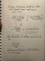
This works for HSS cutters in good condition. If you're using carbide cutters you can get close to tripling the result of that formula depending on the situation (cooling/cutting oil/chip evacuation/etc)

Also, with aluminum I'd recommend using a 2-flute cutter rather than a 4-flute as it will clear chips better and have less tendency to pack up the flutes.

For drilling and milling we're using the diameter of the cutting tool in the formula. If turning a part on a lathe, we're using the diameter of the stock (unless drilling into the end). For reamers, cut the results of the formula in half if you value your reamers!

For insert carbide tooling on a lathe...that formula result * 3 is usually about right. Carbide inserts need a fair depth of cut to work properly too, they are not sharp but instead rip away material via heat and pressure. If you're not generating heat and pressure the insert won't give predictable results.
 
Top Bottom Back Refresh